A Cheaper Home Automation Solution
A while back I set up a little home automation using a USB 433Mhz transmitter to control some RF sockets I had lying around. The primary aim was to replace the timer I used to run my lamps, which needed constant changing throughout the year.
 It worked, and I even made a couple of tweaks to update the timer so that it automatically came on around sunset, thereby switching itself on at an appropriate (ish) time without any interaction from me.
The project wasn't particularly expensive, using a Telldus TellStick that cost about £55. I also needed a computer to trigger it, which I already had. The two combined make it quite expensive if you wanted to start from scratch, and the TellSticks aren't easy to find (in the UK at least). Other alternative USB transmitters are dearer still.
With the arrival of the Raspberry Pi I could solve the issue of an expensive computer, plus reduce the power required. I started looking around and thought I could use a cheap 433Mhz transmitter and use the Pi's GPIO pins to drive it. And so my quest began.
Initial Failure
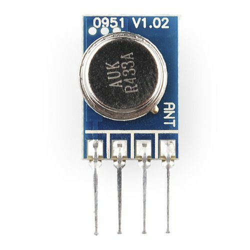
As I said, I had done my research. Google and the Pi forums proved my friend and I soon decided to grab a small 433Mhz transmitter from Amazon, this one in fact. Which cost a rather pricey £5.59 (for this sort of transmitter anyway, see below).
 I also picked up some jumper wires, figuring I could simply attach them onto the GPIO pins and the pins on the transmitter. That didn't go so well. I eventually gave up and purchased a GPIO starter kit off eBay (doesn't look like it's on eBay any more, but you can still buy direct from Smart-Elex, plenty of others are available too).
For £9.50, the kit provided me with a some LEDs, switches, resistors, a heap of jumper cables and, more importantly, an 830 point breadboard, a cable and a GPIO breakout kit (like the Cobbler). This made working on things much easier.
I tried a lot of different libraries (rf-bitbanger, RCSwitch-pi, and others) but couldn't get it work, so gave up and figured I would some back to it later, hoping someone would develop an easier solution.
In hindsight, I had two problems:
- It appears I didn't have my transmitter wired up correctly (there isn't anything on the pins to indicate what does what aside from the antenna).
- I didn't have a receiver to allow me to capture the signals from my handset, so I had to rely on what others had found.
A Second Go
It came back around to me thinking about the project again (thanks to this post) and I started yet more research. I liked the look of pilight (although I found it hard to install, with apt-get failing on me, got there with a git clone). Around this time I figured out my transmitter had been hooked up wrong so was excited to try this new option.
Still no go though. I wasn't even sure if the transmitter was sending anything, so I figured I would order a kit containing a transmitter and receiver, in case I had destroyed my transmitter with the faulty wiring (I hadn't).
 After a bit of research I opted for a pair that seemed to match those in a couple of tutorials. The pack cost £1.89 including postage.
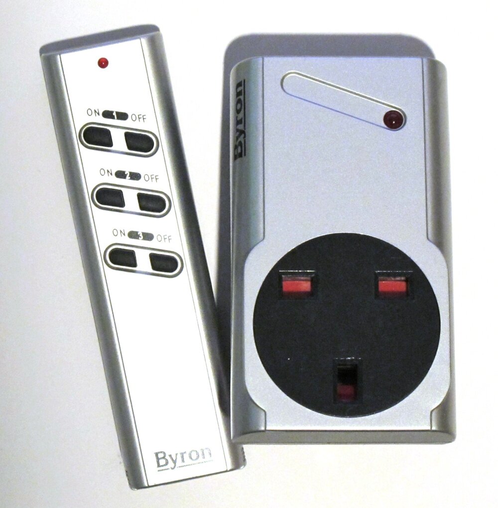
I stuck with my original transmitter and hooked up my receiver. I tried a few of the default protocols, looking again at what my sockets used (they're Byron RS3 units). Everything I could find suggested they used the Bye Bye Standby (BBSB) protocol, which pilight can send as kaku_switch_old (apparently). No joy with that.
The pilight toolset includes a receiver and debugger. So I fired these up and tested my receiver. The good news was I was picking things up, but even without pressing a button the system would register events using receive (and raw just streamed numbers, it may have been a noise issue). Debug did pick up some raw code, but when I tried transmitting it, nothing happened to my socket (the receiver registered it was sending).
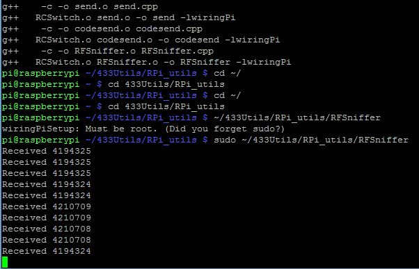
Back to the internet and I found an article on using 433Utils (from Ninjablocks). That enabled me to capture the codes being sent by the handset that came with the sockets. Using this code and the included codesend application in the 433Utils library I was able to turn sockets on and off.
I was worried the range wouldn't be too good, but when I put in the code of a unit attached to my lamp it picked it up fine. That was downstairs and across the other side of the house, ten metres or more.
So I could do it from a command line, but could I do it from a web page, as I do with my existing solution? Well, it took a lot of figuring out, but yes, I finally succeeded in doing so.
A Cheaper Alternative
My original solution was quite pricey, but how did this option compare?
Well, I plugged my TellStick (£55) into my Shuttle XS35 machine (£180), so you could argue it was £235. Equally, I already had the machine, so you could say £55.
For the new solution you're looking at buying a Pi. My Model B seems to be going for around £29 at the moment, but you could pick up a Model B+ for £23 and you should be able to run this on a Model A+ (£19), although you'd need a Wi-Fi adapter too (£5) so it works out about the same. You'd also need a power supply (£7), a memory card (£8) and a case (£5). That's £43 if you went the B+ route. You can pick up a kit of the lot for £36 though (all prices from Amazon and rounded up).
Add to that the cost of the transmitter (£6) and receiver (£2) and you're still under the price of the TellStick (the total coming to £44). I've left off the breadboard kit, but even going high and allowing £10 for something similar brings you in under (£54). That's assuming you buy it all new, there's a chance you have some of these things.
I couldn't find the TellStick available in the UK, only the more expensive models in the range (starting at £70), so we're well inside that cost, even if you don't include a machine to run it on.
Although the XS35 is low power, it still uses far more energy than the Pi, so there's an argument for ongoing running costs being in the new solution's favour as well.
Replicating What I Did
All well and good, but how do you get your system up and running like mine? Well, you're going to need to follow these steps (after purchasing the requisite hardware, obviously).
1. Connect your transmitter and receiver
The connections are fairly simple, you connect a 5v pin (I used pin 2 for both devices) and the ground (pin 6) to the relevant pins on your transmitter and receiver. Then comes data.
I connected pin 17 (GPIO/wiringPi pin 0) to my transmitter and pin 21/27 (depending on whether you have a rev 1 or 2 board, GPIO/wiringPi pin 2) to my receiver. Here's the pin listing from wiringPi for easy reference.

2. Install WiringPi
To install WiringPi on your Pi use:
[code]cd ~/
git clone git://git.drogon.net/wiringPi
cd wiringPi
./build[/code]
Note, Git should already be installed, if not, use
[code]sudo apt-get install git[/code]
3. Install 433Utils
To install the 433Utils kit, use:
[code]cd ~/
git clone git://github.com/ninjablocks/433Utils.git
cd 433Utils/RPi_utils
make[/code]
4. Capture the codes
To capture the codes being sent by your handset, you first need to run the RFSniffer command:
[code]sudo ~/433Utils/RPi_utils/RFSniffer[/code]
With that running, get your handset close to the receiver (like right up alongside) and hit the buttons you want to capture codes for. You may want to make note of the codes as you go, but at least remember the order you pressed them in.
Press CTRL+C to cancel when you're done.
5. Test transmit your codes
You can now test the codes by using the compiled codesend executable, like so:
[code]sudo ~/433Utils/RPi_utils/codesend <your code>[/code]
If nothing happens, check the transmitter is sending by opening a second terminal window and running RFSniffer using the command in the previous step. Try to send the code again and you should see something appear in the sniffer window, if it's working.
If you don't see anything, check your wiring. If you are sending, but the device isn't responding, try moving it closer to eliminate range, or try capturing the code again to make certain it's the correct one.
6. Controlling it from a web page
Assuming you're now up and running, congratulations, you're now able to control your sockets from the command line. It's not a lot of use yet. You can enable the codesend command to be made from an application. Here though, I will discuss how to create a web page that can send both the on and off commands (and if you can do it from a web page you can call it from a cron task to schedule it, all sorts).
To do this, you first need to install the LAMP stack (you only really need Apache and PHP, but MySQL will come in handy if you want to build more functionality around it).
On a clean Raspbian install, apt-get struggled for me, so I would suggest running this first:
[code]sudo apt-get update[/code]
Then run:
[code]sudo apt-get install apache2 libapache2-mod-php5 php5 php5-mysql mysql-client mysql-server[/code]
You'll need to say yes to confirm the install, then pick a MySQL root password at the prompt.
To confirm it's installed, open the web browser and type 127.0.0.1 into the address bar (from the Pi itself, or put the Pi's IP address into the browser on another device). You should see a page stating: "It works!"
7. Open access to the GPIO ports
By default, you can't trigger the codesend command from a web page because WiringPi requires root privileges to run. To get around this you can export the pin you require. This can be done by opening rc.local using:
[code]sudo nano /etc/rc.local[/code]
Modify it by adding:
[code]sudo -u www-data /usr/local/bin/gpio export 17 out[/code]
before the last line (the one stating):
[code]exit 0[/code]
So you have:
[code]sudo -u www-data /usr/local/bin/gpio export 17 out
exit 0[/code]
Press CTRL+X, type y and hit Enter to save the changes. This will export the pin each time the Pi is rebooted, so next you need to reboot the Pi with:
[code]sudo reboot[/code]
Once this is done, you need to modify the codesend executable to change the pin number and use a slightly different WiringPi function. To do that, you need to edit the original file with:
[code]cd ~/433Utils/RPi_utils/
sudo nano codesend.cpp[/code]
Then change:
- int PIN = 0; to int PIN = 17;
- wiringPiSetup to wiringPiSetupSys
We you've done this, exit and save. Now rebuild the executable by running:
[code]make[/code]
Finally, you need to grant the www-data user (the web server) permissions on the GPIO ports. Not sure if this is the best approach, but I ended up going this route:
[code]sudo chown -R root:gpio /sys/class/gpio
sudo adduser www-data gpio[/code]
8. The End Result
So how do you then implement this, well I've put together a quick example.
Open the file and modify the relevant RF codes for $on_code and $off_code, then save as index.php under /var/www.
Open your browser and point to your Pi (127.0.0.1 if on the actual machine) adding /index.php to the end. Then simply click the ON or OFF links to trigger the codesend.
Summary
So there you have it, a web page that can control a socket (or anything else). I use mine to control a lamp on a timer, but it could be used to do all sorts of things. Obviously you can expand this to run at specific schedules or however you wish. Once you can send the signal from code, it opens up a ton of possibilities.